Welded closed
Arcing or severe inrush can fuse contact surfaces, leaving voltage downstream after an open command.
High-voltage contactors are heavy-duty, electrically controlled switches inside the battery junction area. They keep the traction battery isolated while the vehicle is parked, then connect it only after the safety checks and pre-charge sequence succeed.
Most EV battery packs use at least a main positive and a main negative contactor. A separate pre-charge contactor and resistor create a controlled first connection before the main path carries full current. The exact layout and closing order vary by manufacturer.
When the car requests ready mode or charging, the battery management system checks conditions such as isolation, interlocks, voltage and crash status. It then drives the contactor coils and watches whether the high-voltage bus responds as expected.
A contactor is more than an audible click. Contacts can be burnt, resistive or welded; a coil or driver can fail; feedback can disagree; and an external high-voltage fault can make a healthy contactor appear to be the problem.
These illustrations show the principle. Contactor position, polarity, switching order and service access are always vehicle-specific.
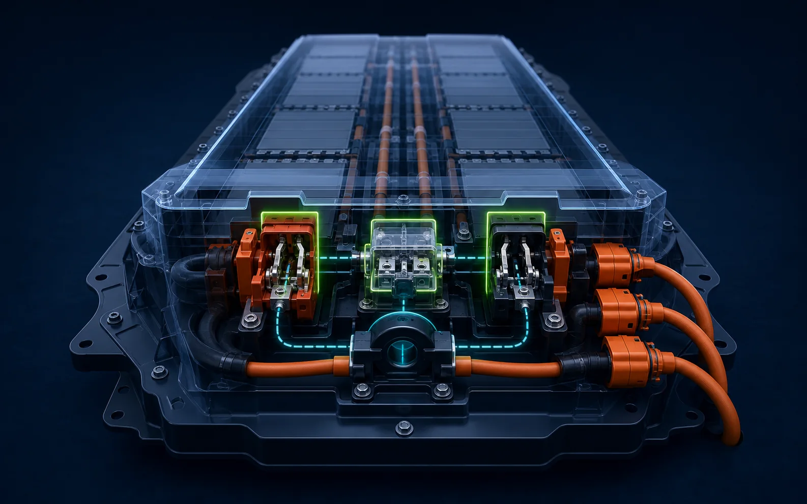 01
01
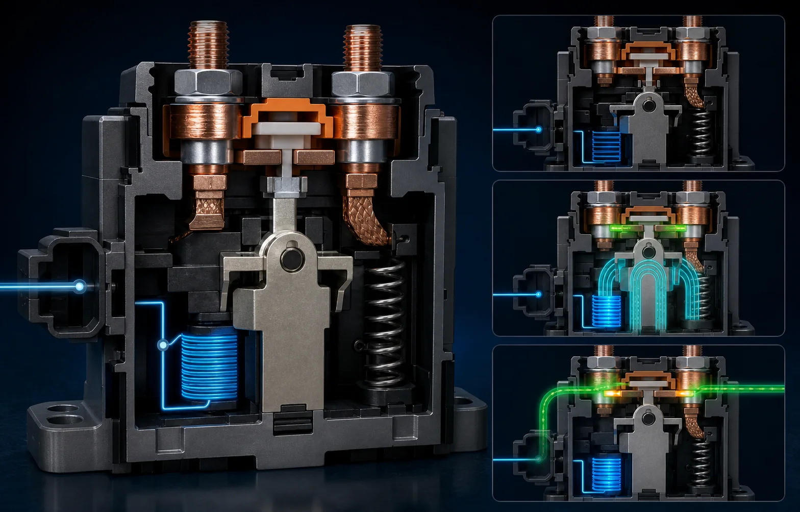 02
02
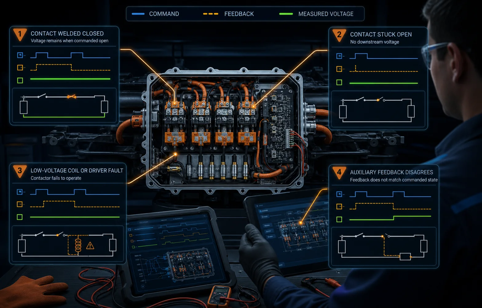 03
03
Good diagnosis separates the power contacts, the coil command, the monitoring circuit and the rest of the HV system.
Arcing or severe inrush can fuse contact surfaces, leaving voltage downstream after an open command.
Burnt contacts, mechanical failure or a broken connection can prevent the HV bus from energising.
The contactor may be mechanically sound but never receive the correct low-voltage drive.
An auxiliary contact, sense wire or module input can report the wrong physical state.
Pitted contacts can still close but generate heat and a measurable voltage drop under load.
A shorted load, failed pre-charge path or incorrect bus reading can prevent an otherwise healthy sequence.
HV contactor work requires trained personnel, the correct PPE and the manufacturer shutdown and verification procedure.
Record all module codes, freeze frames, battery and bus voltage, isolation status, interlock status and whether the issue occurs during ready, charging or shutdown.
Use live data and approved measurement points to compare the requested contactor states with pre-charge progress and downstream HV voltage.
Confirm the 12-volt supply, ground, coil resistance and driver command only where the OEM procedure permits. A click alone is not proof of a good circuit.
A closed command should agree with auxiliary feedback and the expected HV voltage. An open command should leave the system in its specified isolated state.
Where authorised, voltage-drop, resistance or thermal evidence can expose worn contacts or cable and junction resistance that a static check misses.
After the approved repair, repeat ready, shutdown and charging checks, confirm correct pre-charge timing and ensure no unexpected HV remains downstream.
| Observed evidence | What it may indicate |
|---|---|
| Command closed, bus stays low | An open contactor, missing coil drive, failed pre-charge path, cable fault or a load pulling the bus down may be involved. |
| Command open, bus stays high | Welded contacts are possible, but stored charge, another connected source or an incorrect voltage signal must be considered. |
| Feedback disagrees | The contactor may not have moved, or its auxiliary contact, wiring or monitoring input may be faulty. |
| Voltage drop under load | High resistance can exist across worn contacts, internal joints, fuses, cables or terminals. Compare against OEM limits. |
| Intermittent on bumps or heat | A marginal coil, terminal, driver, auxiliary contact or mechanically worn contactor may change with vibration or temperature. |
Those sounds can be the battery contactors and related relays operating. A normal sequence varies by vehicle, and an audible click does not prove the power contacts are electrically healthy.
Yes. Many vehicles need the battery contactors to establish the correct high-voltage path for charging, ready mode or both. The precise architecture depends on the model.
Severe inrush, switching under abnormal current, repeated arcing or a fault elsewhere in the HV system can damage the contact surfaces. The cause must be found before fitting another part.
No. Some packs allow approved junction-box or contactor repairs, while others have different service policies. The fault first needs proving and the manufacturer repair method checked.
Send us the full scan, vehicle details and exactly when the fault occurs. We can assess the contactor, pre-charge and wider HV evidence together.