State of charge
Voltage, current integration, temperature and learned behaviour contribute to the displayed battery level.
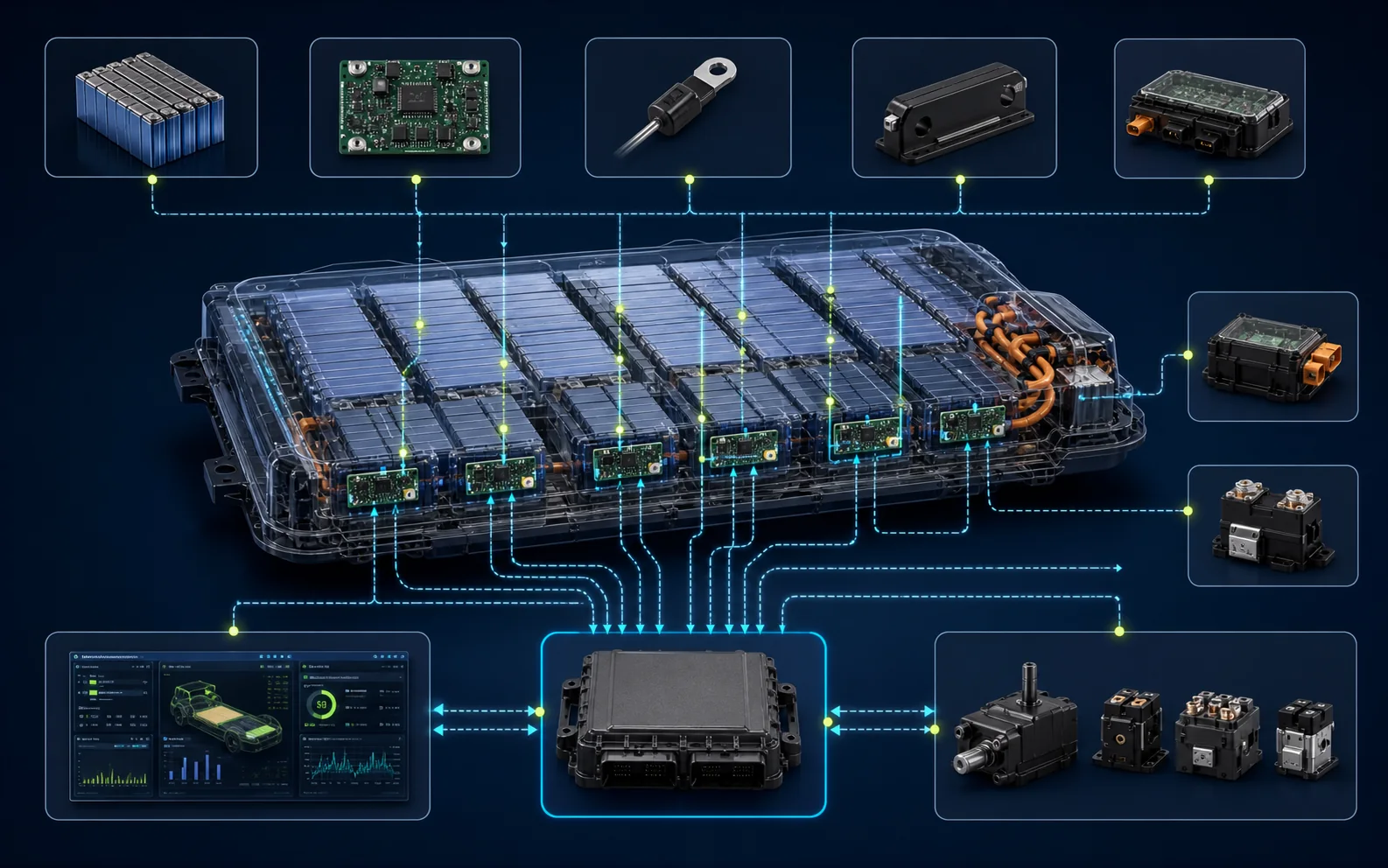
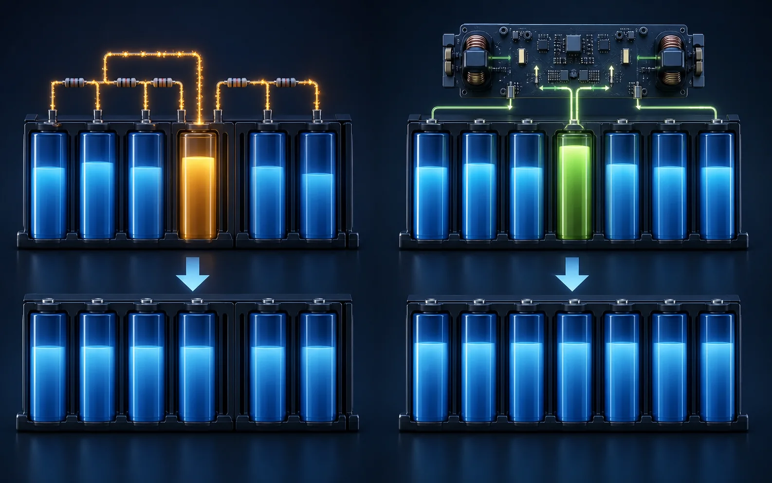
The BMS monitors cell-group voltages, current and temperature, estimates battery state, controls contactors and sets charge and discharge limits. Cell balancing helps the groups finish charging together—but it cannot repair a genuinely weak cell.
Cell-monitoring circuits measure series groups throughout the pack, while pack sensors measure current and multiple temperatures. Depending on the architecture, the BMS also receives isolation, coolant, pressure, crash and high-voltage interlock information.
Software combines these inputs to estimate state of charge, state of health and available charge or discharge power. These are calculated values rather than a direct fuel-tank reading, so sensor accuracy, calibration, temperature and learned history matter.
The BMS also controls or supervises contactors, cooling and balancing. If one cell group reaches its upper or lower limit before the rest, that weakest usable group can limit the entire series pack.
The number and location of monitoring boards vary, but the core task is consistent: trustworthy measurement followed by safe control.
 01
01
 02
02
 03
03
Its decisions affect range display, performance, charging, thermal control and whether the vehicle can energise high voltage.
Voltage, current integration, temperature and learned behaviour contribute to the displayed battery level.
Usable capacity, resistance and performance history can contribute to battery-health estimates.
Charge and discharge limits adapt to temperature, voltage, state of charge and fault conditions.
The BMS supervises pre-charge and isolation of the high-voltage battery.
Sensor data supports battery pumps, fans, valves, heaters and charge conditioning.
Small voltage or charge differences are managed, commonly near the upper state-of-charge region.
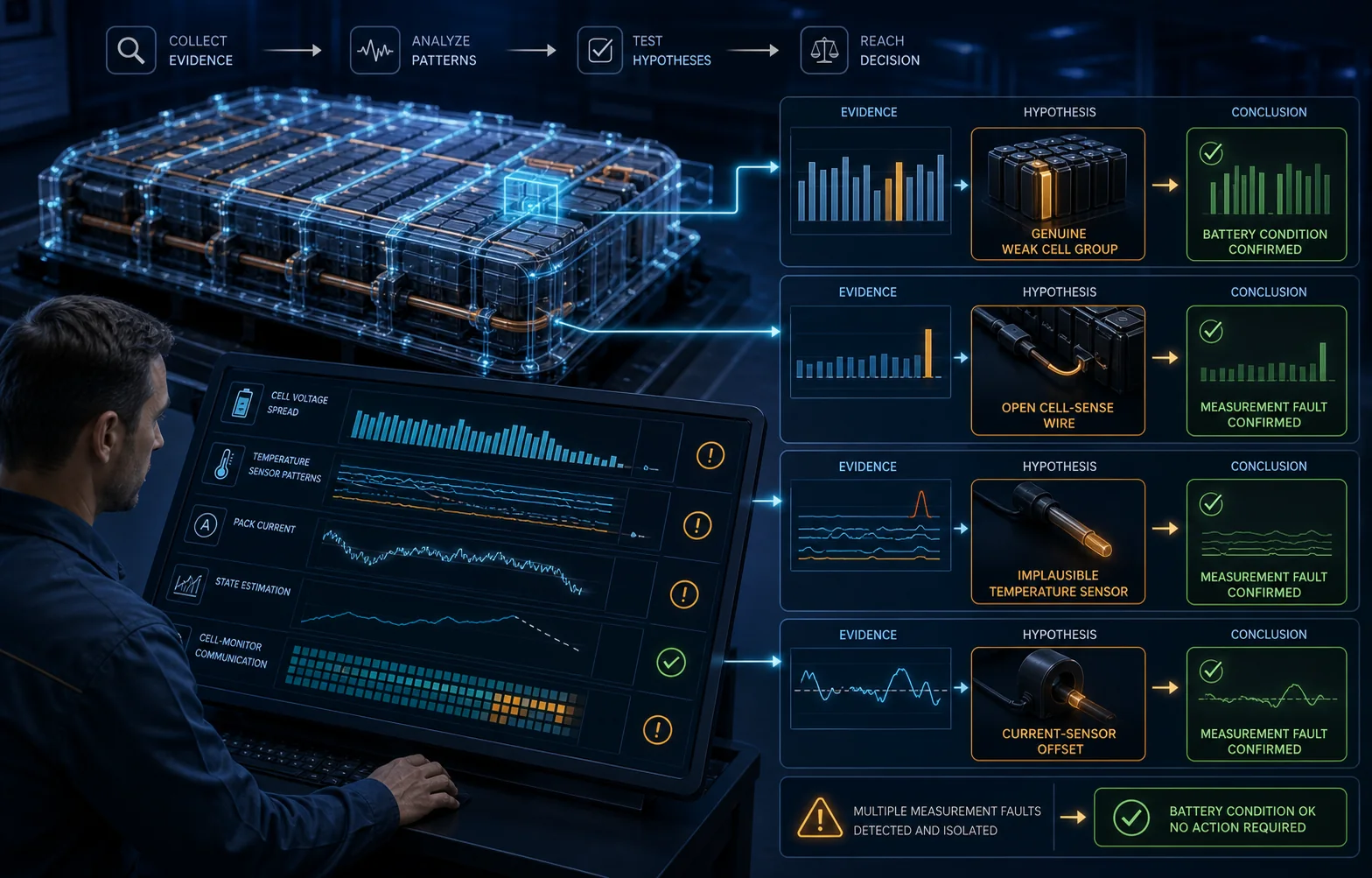
Replacing cells or a BMS from one scan value risks repairing the measurement instead of the fault—or the fault instead of the measurement.
Capture the full vehicle scan, freeze frames, cell-group voltages, temperature sensors, pack current, isolation data, state of charge and power limits before clearing or charging.
Compare all cell groups and sensors after a suitable stabilisation period. An impossible step change or outlier can indicate a sense or communication issue.
A weak group may show greater voltage sag during acceleration and recover differently at rest. The test must stay within safe manufacturer limits.
A low-capacity or high-resistance group may reach the upper voltage limit early, causing charge taper or termination before the rest of the pack.
Following safe isolation, approved checks of sense leads, connectors, monitor supply, temperature inputs and module communication can validate the reported value.
After an authorised repair, perform required programming, balancing, capacity or state-of-charge routines and confirm consistent data across real driving and charging conditions.
| Data pattern | What it may mean |
|---|---|
| One group sags under load | Lower capacity, higher internal resistance or a connection issue may be present; repeatability and measurement integrity must be checked. |
| One value jumps instantly | A sense wire, connector, monitoring channel or communication fault may be more likely than a cell changing instantly. |
| One group reaches full early | Imbalance, reduced capacity or resistance can cause that group to limit the whole charging session. |
| Temperatures disagree | A genuine local hot or cold area, sensor bias, poor thermal contact or wiring fault needs separating. |
| State of charge drifts | Current-sensor offset, learned-capacity error, calibration, cell imbalance or ageing can influence the estimate. |
No. Balancing can align the state of charge of cell groups, but it cannot restore lost capacity, reverse high internal resistance or repair physical damage.
The groups are connected in series. Charging must stop before any group exceeds its upper limit, and discharge must be restricted before any group falls below its lower limit.
Not like liquid in a tank. The BMS estimates it using current, voltage, temperature, calibration and learned battery behaviour.
No. A real weak cell is possible, but the sense connection, monitoring channel and operating conditions must be checked. The way the value behaves under load and charge is important evidence.
Send us the vehicle details, full scan and any cell data you have. We can plan a controlled battery-health and BMS investigation.