Relay fails open
The pre-charge path is never established, so the DC-link voltage may remain near zero.
Before an EV makes its full high-voltage connection, pre-charge gently fills the capacitors in the inverter and other HV electronics. Without that controlled step, the initial current could damage contactors, fuses, cables and capacitors.
The inverter, onboard charger, DC-DC converter and other HV electronics contain capacitors that smooth and stabilise their DC supply. When discharged, they can draw a very large instant current if connected directly to the traction battery.
A pre-charge relay or contactor routes current through a resistor first. The vehicle measures the increasing DC-link voltage, and once the required threshold is reached within the permitted time, it closes the main path and removes the resistor from continuous duty.
The exact contactor order, target percentage and time window are manufacturer-specific. Diagnosis therefore focuses on the commanded sequence and the measured voltage curve—not a universal timer or one relay code.
The sequence shown is conceptual. Always use the circuit diagram, timing and limits for the exact vehicle.
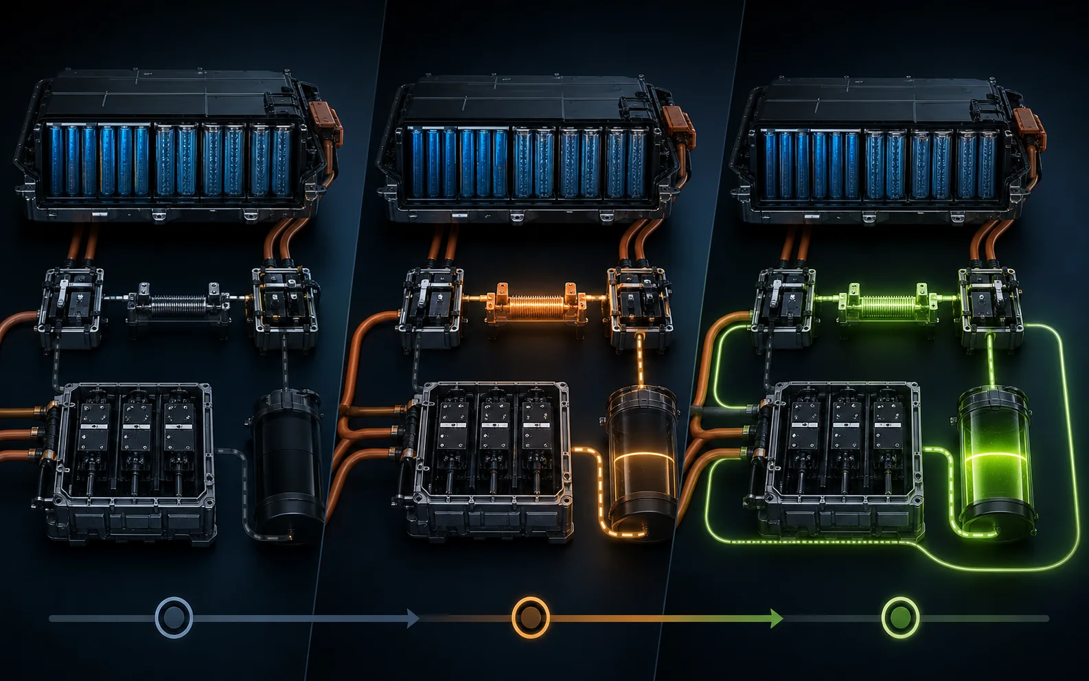 01
01
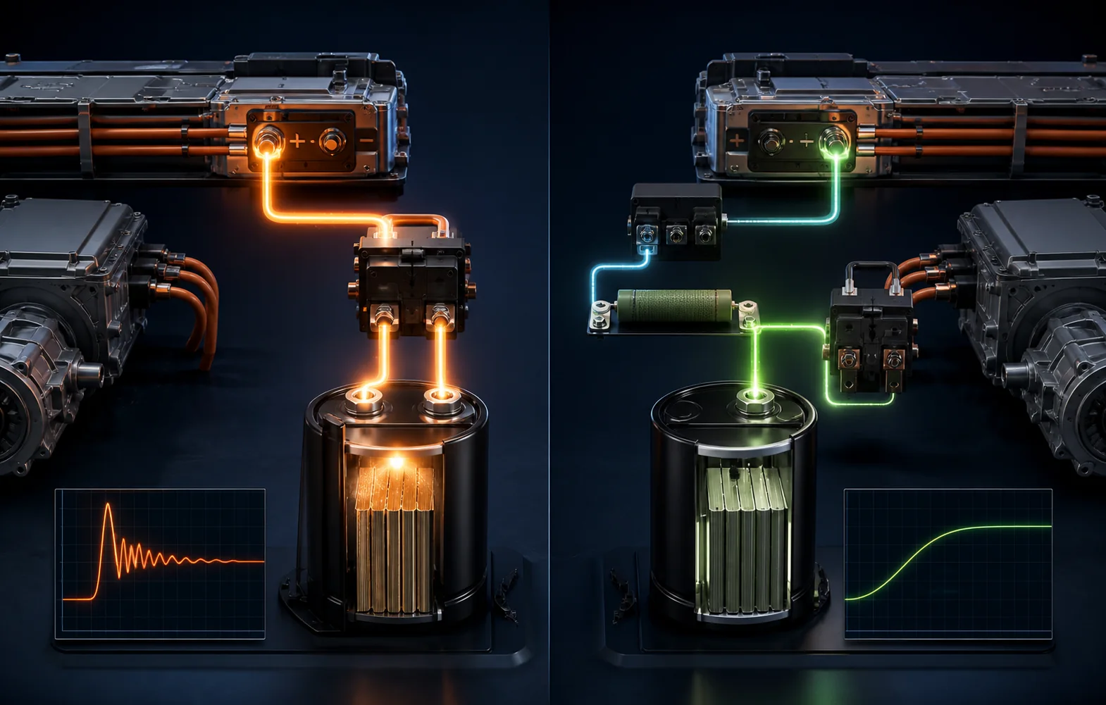 02
02
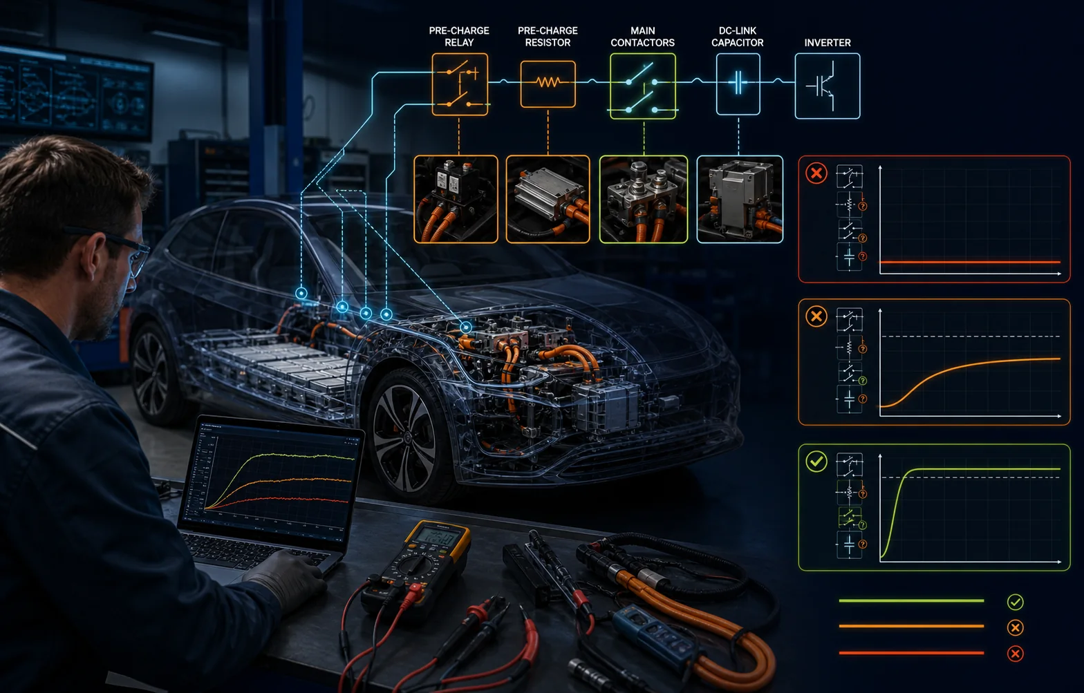 03
03
A pre-charge code is an outcome. Several electrical, control and load-side faults can create it.
The pre-charge path is never established, so the DC-link voltage may remain near zero.
A cracked resistor or poor junction can prevent or excessively slow the voltage rise.
An uncontrolled connection can produce excessive inrush and damage the main switching path.
A connector, internal busbar, fuse or cable can interrupt the intended current route.
A leaky or shorted inverter, charger or other HV component can pull the voltage down.
The voltage may rise correctly while a sensor, reference, wiring or controller reports otherwise.
A correct investigation uses the OEM sequence, live data and approved measurements while maintaining full HV safety controls.
Record whether the issue appears at ready request, charging, rapid charging or after previous repair, and preserve all related module codes and freeze frames.
At the start of the command, establish the battery-side voltage, downstream bus voltage and the manufacturer-expected relationship between them.
Watch how quickly and how smoothly the bus voltage rises. No rise, a slow rise, a collapse or an instant jump each suggest different checks.
Compare the requested states of the main and pre-charge contactors with auxiliary feedback and the actual voltage response.
Following isolation and proof of absence of voltage, check the relay, resistor, fuse, connections and wiring only as the service information directs.
If the pre-charge hardware is intact, determine whether an inverter, charger, DC-DC converter or other DC-link component is absorbing or leaking the charging energy.
| Voltage behaviour | Diagnostic direction |
|---|---|
| No voltage rise | Look for missing command, open relay, resistor, fuse, wiring or a severe downstream fault. |
| Rises too slowly | Excessive series resistance or an abnormal load may prevent the bus reaching its target within time. |
| Rises then collapses | The main path may not take over, a contactor may open, or the DC-link load may pull voltage down. |
| Instant uncontrolled jump | A welded or bypassed path, incorrect switching order or sensing issue needs urgent investigation. |
| Data and meter disagree | Check voltage sensing, reference, communication and measurement location before condemning hardware. |
Usually no. The pre-charge device controls a lower-current path through a resistor, while the main contactors carry full operating current. Designs vary, so the exact circuit diagram matters.
DC-link capacitors smooth the high-voltage supply and handle rapid energy changes as the inverter switches power to and from the electric motor.
Yes. If a connected HV component loads the bus abnormally, the voltage may not rise as expected even when the relay and resistor are functioning.
No. The code does not prove which element failed. The command, voltage curve, contactor state, resistor path and connected DC-link components need checking.
Share the vehicle details, complete scan and when it fails. We can investigate the pre-charge path, contactors and downstream HV load safely.